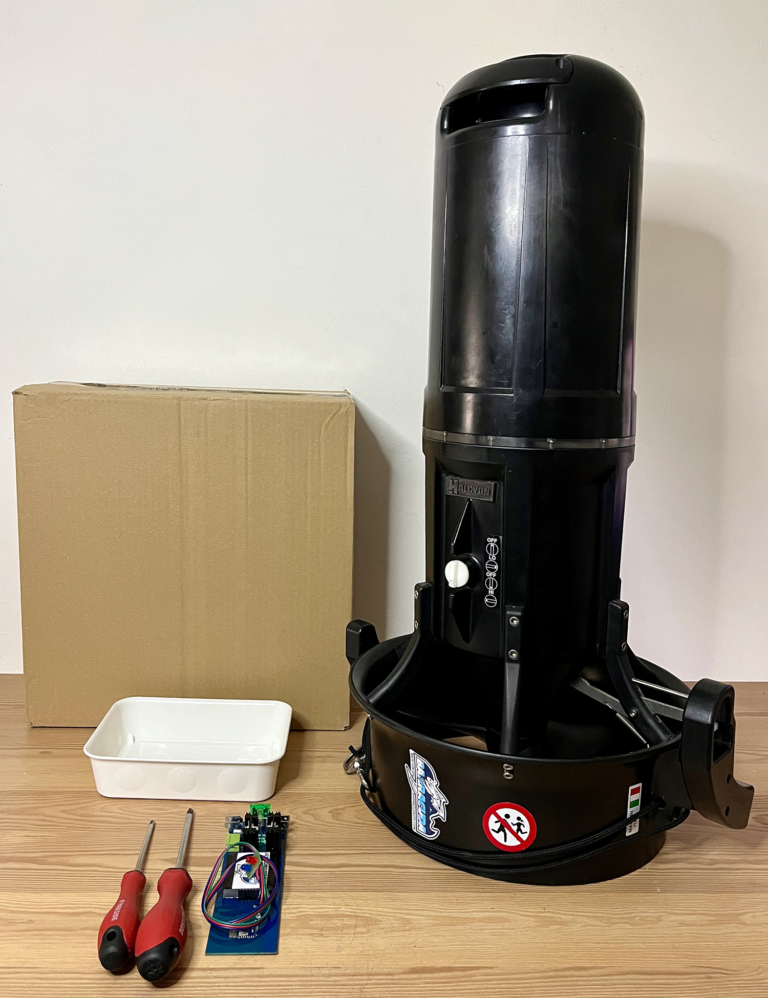
The installation involves replacing the original control board with a DPV Speed Controller BT. For the replacement you will need: – 2 Phillips screwdrivers in sizes PH2 and PH0 – a container for the screws – a box about 40-45 cm high to support the baffle – vaseline and a cloth.
The colors of the wires, connector covers and the appearance of the original Suex control board may vary depending on the scooter model.
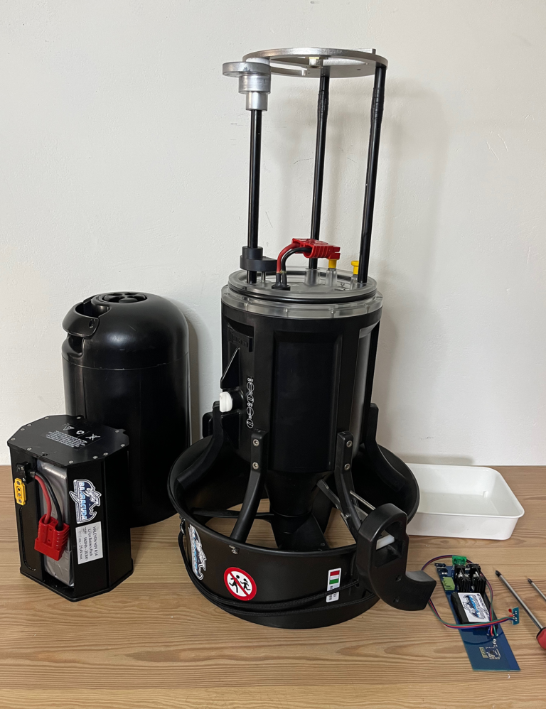
Step 1.
Remove the top cover of the scooter, remove the battery and the strain relief (if installed) and remove the sealing o-ring.
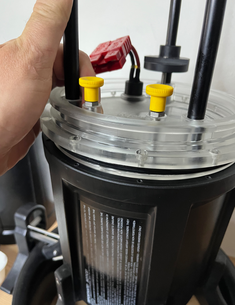
Step 2.
Use a PH2 Phillips screwdriver to remove the 12 screws holding the motor baffle.
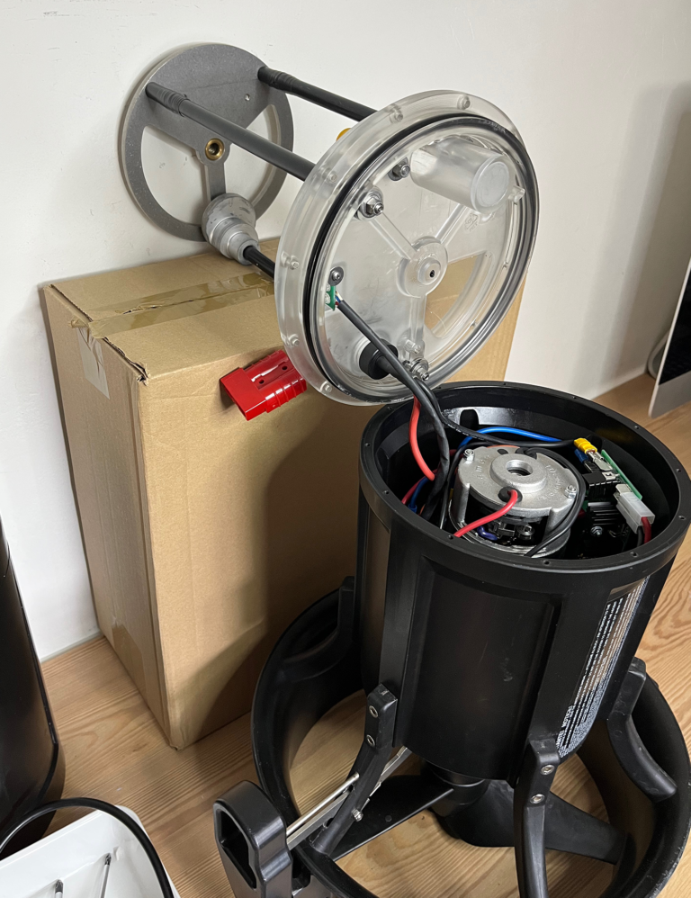
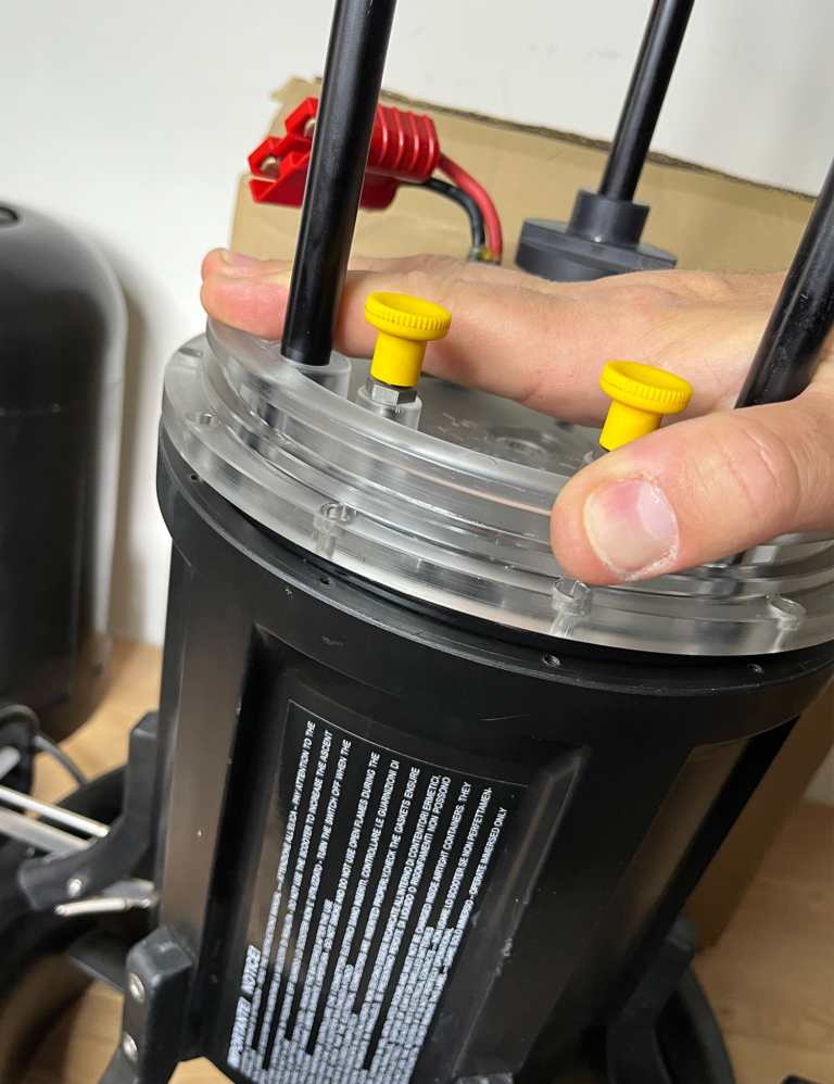
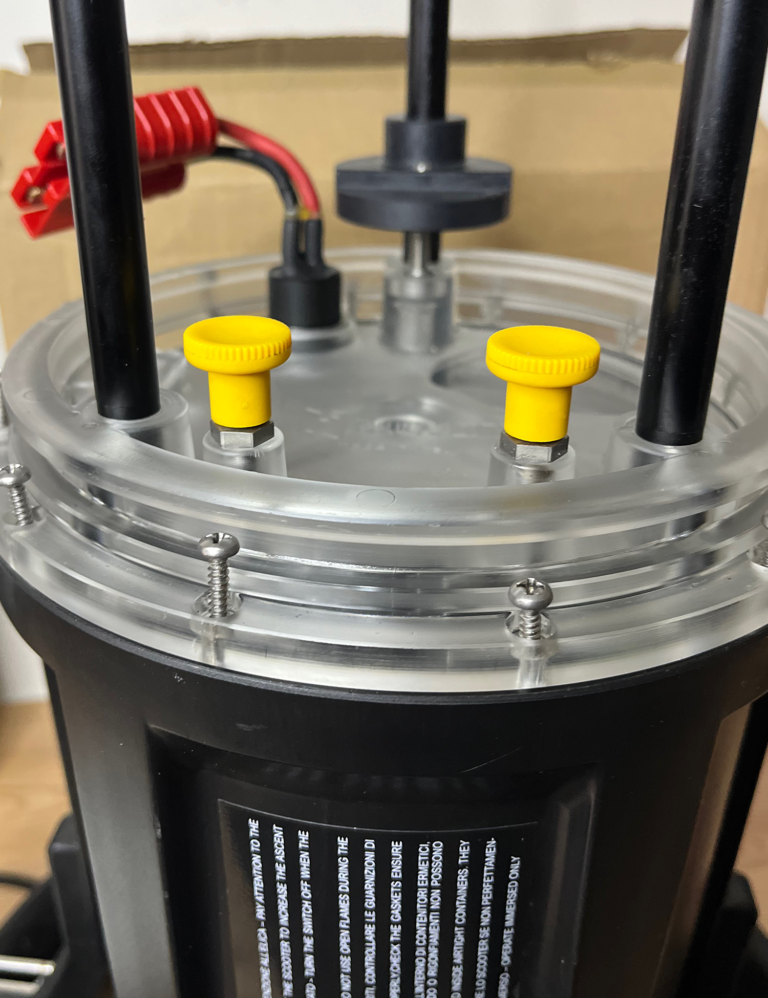
step 3.
Lean the carton stably against the wall, e.g. turn the scooter with the switch towards the carton, pull the baffle from one side up to open the motor part (IMPORTANT! do not lever the baffle with anything hard). Lean the baffle with the gasket against the edge of the scooter housing and the remaining part against the cardboard.
Step 4.
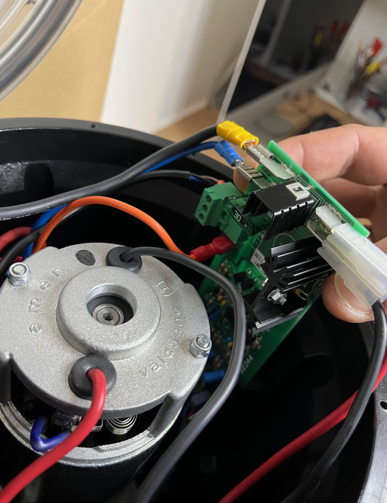
Slide out the control board and disconnect all the connectors from it (it’s a good idea to take a photo of how the wires are connected beforehand, it will come in handy during assembly).
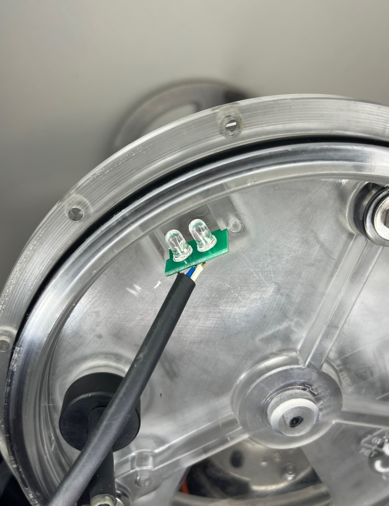
step 5.
Using a PH0 Phillips screwdriver, remove the board with transparent LEDs.
Step 6.
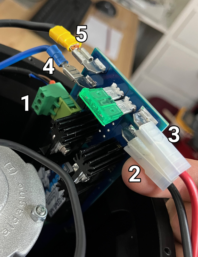
In place of the original board, insert the DPV Speed Controller BT plug in the following order:
1. 3-pin inductive switch connector 2. Connector (–) Motor 3. Connector (+) Motor 4. Connector (+) Battery (operating from the switch) 5. Connector (–) Battery (directly from the battery).
Do not connect the “VELOCITA RIDOTTA” cable, originally responsible for low speed (we secure the cable connector inside the scooter).
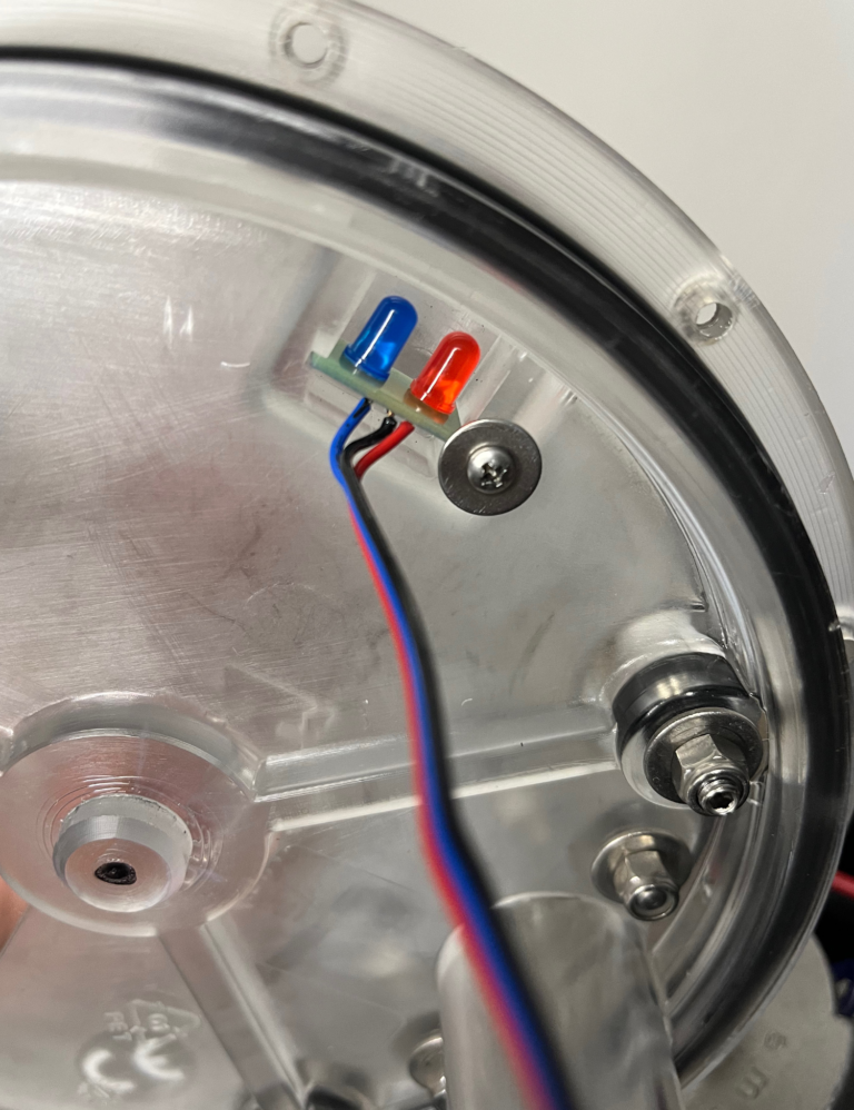
STEP 7.
Install the board with colored LEDs analogously as originally.
STEP 8.
If maintenance requires it, clean and lubricate the baffle o-ring and tighten it, trying to maintain proper alignment with respect to the holes.
Insert the screws in their proper places and tighten them in a star pattern sequence, that is, tightening first one screw on one side and then the opposite (not the next). Tighten the screws sensitively until the baffle is in contact with the housing.
The END.
If maintenance requires it, clean the groove and lubricate the top cover’s o-ring.
Install the battery and check the operation of the controller.
We use cookies to ensure that we give you the best experience on our website. If you continue to use this site we will assume that you are happy with it.

