Installation of the DPV Speed Controller involves removing the relay that controls the motor, and connecting the controller in its place.
Before proceeding with the installation, familiarize yourself with all the steps outlined below. The wiring connections shown are only a suggestion.
The installation time takes about 10 minutes. The photos used in this tutorial were provided by one of the DPV Speed Controller users. (Thank you Hubert).
The installation method of DPV Speed Controller V1 and V2 is the same.
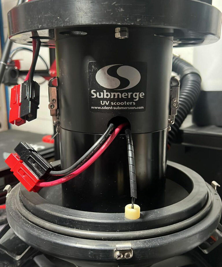
Step 1.
We remove the base with the battery.
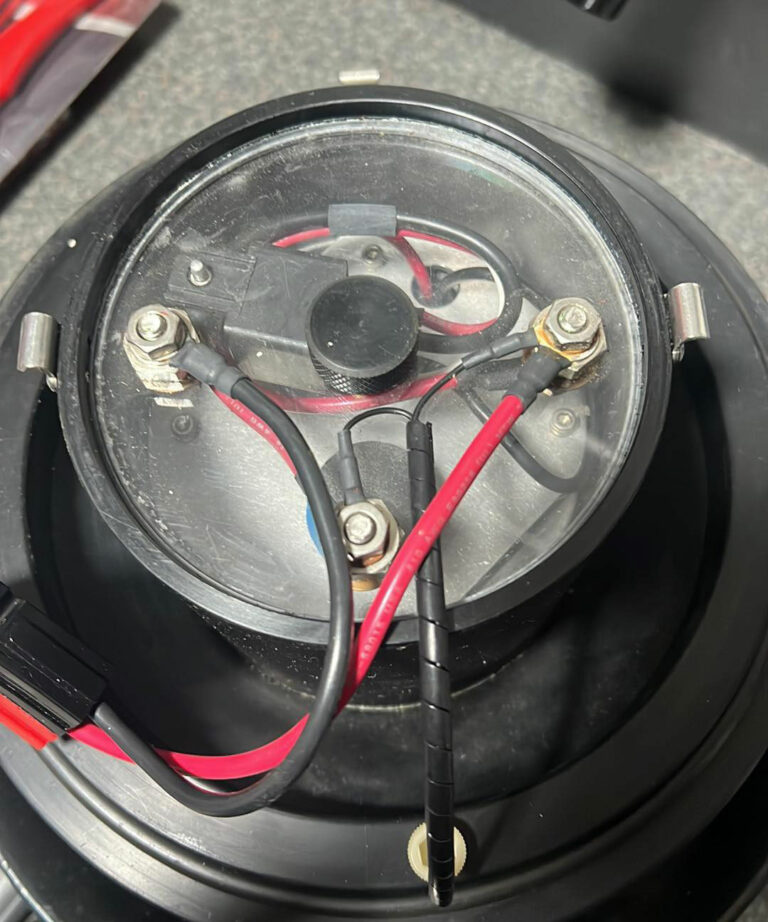
We unscrew all the wires from the baffle.
We remove the black plastic screw (in the middle).
Using compressed air or a pump (e.g. foot pump for the mattress) – blowing inside the engine compartment, we push out the baffle (a more drastic option – we pull the metal screws with a pair of pliers, being careful not to damage the threads).
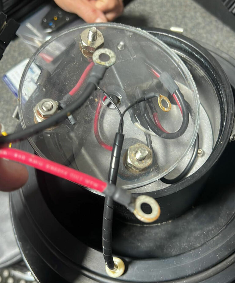
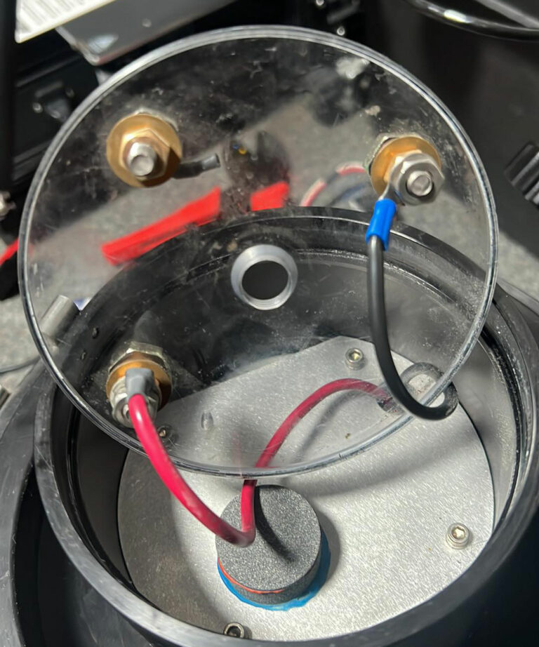
Step 2.
Cut the power wires from the eyelet connectors and the thin black wires going to the reed switch.
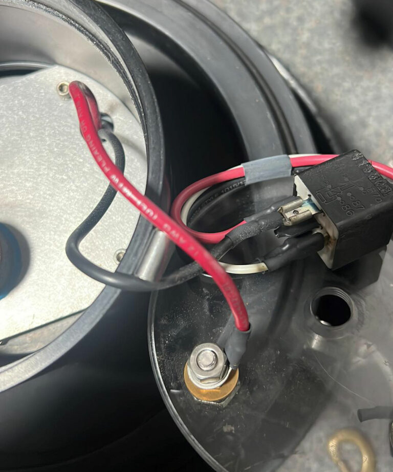
step 3.
We cut the black motor wire connected to the relay from the connector.
We unscrew the wires screwed to the screws in the baffle, leaving only the red motor wire screwed in.
We unscrew and remove the relay along with the wires.
Step 4.
On the end of the black motor cable, attach and crimp the eye connector (included in the kit).
We screw the black motor cable under the free screw
We close the baffle.
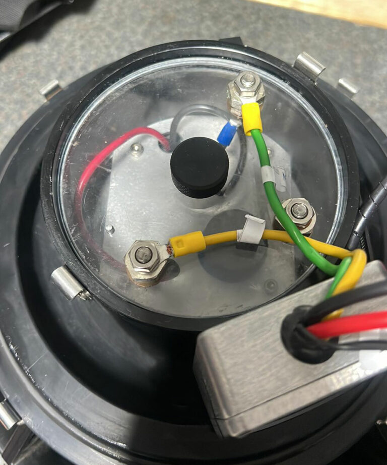
step 5.
Connect the controller wires via screw connectors to the corresponding motor wires, yellow to red and green to black.
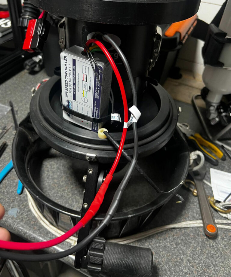
Step 6.
Connect the power wires (cut from the eyelet connectors in step 2) to the controller. To connect, we can use a high-current terminal strip (included in the kit) or connect the wires directly (not forgetting the proper insulation).
NOTE! In order to protect the controller from damage (e.g. in case of a short circuit or reverse connection of the power supply), it is recommended to install a 30A fuse (if the installation is not equipped with one).
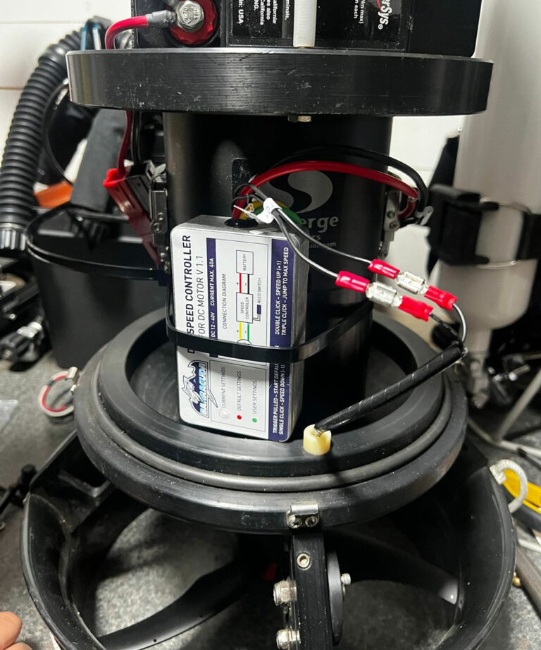
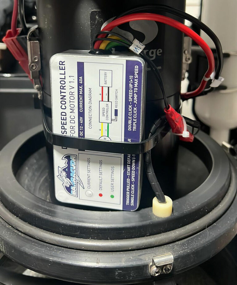
NOTE!When using the scooter, DPV Speed Controller should be mounted in a stable manner (preventing movement) and any exposed connectors supplying power to both the controller and the motor (e.g., connectors (screws) supplying power to the motor on Silent Submerge scooters) should be insulated. Contact between the metal housing of the controller and an exposed power connector can cause permanent damage to the controller.
STEP 7.
Connect the trigger wires of the reed switch (cut off from the eyelet connectors in step 2) to the controller. To connect, we can use a small terminal strip (included in the kit) or connect the wires directly (not forgetting proper insulation) – here we used flat connectors.
The END.
Installation completed after connecting the power supply, you can test the operation of the controller.
Be very careful when starting up for the first time.
We use cookies to ensure that we give you the best experience on our website. If you continue to use this site we will assume that you are happy with it.